Marine Cylinder Liner Gauge
1. Zero Calibration
- Step 1: Insert the zero-setting tool to depress the bore gauge thimble
- Step 2: Rotate the dial until the main needle aligns with “0”
- Verification: Confirm zero point is accurately set before measurement
2. Height Adjustment
- Optimal Position: Set measurement point 5mm below piston ring edge
- Adjustment Method: Turn the nut on the screw eye to fine-tune probe height
3. Measurement Process
- Preparation:
- Thoroughly clean cylinder liner surface
- Clear scavenge ports of debris
- Positioning:
- Place measuring tool according to guide marks
- Ensure bore gauge remains perpendicular to liner surface
- Reading: Record measurements at both front and rear reference points
4. Safety Protocol
Prior to measurement, implement LOCKOUT/TAGOUT:
- System Shutdown:
- Disable start mechanism
- Secure starting air valve CLOSED
- Fluid Isolation:
- Shut off fuel supply
- Drain lubricating oil system
- Mechanical Safeguards:
- Engage gear turning device OFF
- Block cooling water circulation
- Lock turbocharger rotor
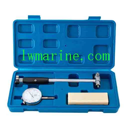
How to Use a Marine Inside Micrometer (Bore Gauge)
Precautions
1. Purpose & Applications
A marine inside micrometer (bore gauge) is designed for precision measurement of internal diameters, such as engine cylinders, bearings, or pipe bores. It is widely used in ship maintenance, marine engineering, and mechanical inspections to ensure dimensional accuracy and compliance with specifications.
2. Key Components
- Anvil & Spindle: The measuring faces that contact the bore surface.
- Thimble & Sleeve: The graduated scales for reading measurements (main scale in mm, thimble scale in 0.01 mm increments).
- Extension Rods: Used for measuring larger bores by connecting to the main body.
- Lock Nut: Secures the spindle in place after adjustment.
- Ratchet Stop: Ensures consistent measuring force for repeatability.
3. Step-by-Step Usage
- Calibration (Zeroing)
- Close the anvil and spindle until they touch.
- Rotate the thimble until the zero line aligns with the reference mark on the sleeve.
- If misaligned, adjust using the calibration screw or consult the manufacturer’s instructions.
- Measurement
- Select the appropriate extension rod (if needed) and attach it to the main body.
- Insert the gauge into the bore at a slight angle to avoid jamming.
- Center the gauge and rotate it 180° to find the minimum dimension (true diameter).
- Tighten the lock nut gently to hold the measurement.
- Reading
- Read the main scale (sleeve) for whole millimeters.
- Read the thimble scale for fractional millimeters (0.01 mm increments).
- Add both readings for the final measurement (e.g., 25.50 mm).
4. Key Precautions
- Avoid Thermal Expansion: Do not handle the gauge with bare hands for extended periods; temperature differences can affect accuracy.
- Prevent Damage: Do not drop or apply excessive force, as this can bend the spindle or anvil.
- Clean Before Use: Wipe the bore and gauge with a clean cloth to remove debris or oil.
- Store Properly: Keep in a dry, protective case to prevent rust and contamination.
- Regular Inspection: Check for wear, calibration drift, or damaged scales before use.
5. Maintenance Tips
- Lubrication: Apply a thin coat of anti-corrosion oil to the spindle and anvil after use.
- Avoid Magnetic Fields: Store away from magnetic tools to prevent interference with precision components.
- Professional Calibration: Send for recalibration annually or as per manufacturer guidelines.
By following these steps and precautions, marine engineers can ensure accurate and reliable measurements, extending the lifespan of both the gauge and the machinery being inspected. inspected.
Attention please: The description was copied from different cooperating manufacturers. The description may be different with the goods, please check with us when order.
Tag: Our other products
Click here to contact us via whatsapp