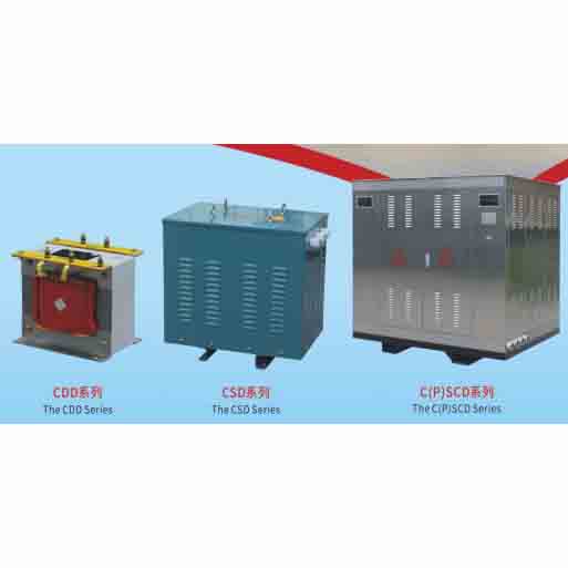
Marine Transformer
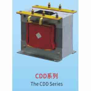
CDD Series – The CDD Series
CSD Series – The CSD Series
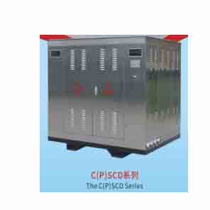
C(P)SCD Series – The C(P)SCD Series
Product Overview
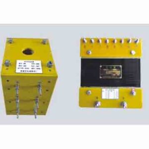
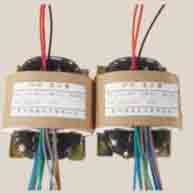
CDD, CSD, C(P)SCD series transformers are normally installed on ships, ocean platforms and other places, and are used for lighting, isolation safety, secondary electrical control, power equipment, etc. This series of transformers are suitable for voltages below 11kV, with frequencies of 50Hz and 60Hz, and insulation classes can be B, F, or H.
Single-phase CDD series capacity: 0.5~10KVA, voltage level below 750V, protection level: IP00.
Three-phase CSD series capacity: 1~400KVA, voltage level below 750V.
Three-phase C(P)SCD series capacity: 100~2000KVA, protection levels: IP22, IP23, IP44 or waterproof IP55 type.
Our company focuses on the design and manufacturing of special purpose products and can produce all kinds of special requirement products according to customers’ requirements.
Model And Its Meaning
(Diagrammatic layout based on the image)
-
First letter: C = Marine use; P = Non-marine platform use (can be left blank)
-
Second letter: D = Single-phase; S = Three-phase
-
Third letter (optional): C = Epoxy resin cast, writeable; E = Non-epoxy resin cast, not writeable
-
Fourth letter (optional): D = Low voltage withstand, not writeable
-
First number: – 10 = Rated capacity: KVA
-
Second part (optional): IP55 = Protection type: S = Waterproof; D = Anti-splash
(Example shown in image: A transformer with Marine use, Three-phase, Cast resin, Rated capacity 10KVA, Waterproof type IP55)
Normal Use Conditions
-
Ambient temperature: -25~+45℃.
-
Relative humidity of air: not more than 95%.
-
Salt fog, mold, and corrosive media are not present.
-
Shocks and vibrations generated during the normal operation of a ship are present.
-
Ships sailing in the case of trim angle ≤22.5°, transverse inclination angle ≤15°.
-
The voltage supply waveform is approximately sinusoidal, and the supply voltage for three-phase transformers is approximately symmetrical.
Product Basis According To Relevant Standards
-
China Classification Society “Rules for Classification of Sea-Going Steel Ships” (2025) and its Amendment Notice 4, Chapter 3.
-
China Classification Society “Rules for the Inspection of Electrical Products” – E-07 (2025).
-
CB/T1001-92 “Marine Transformers”.
-
IEC60076, IEC60270, IEC60068, IEC60529 international electrical and electronic related standards.
Product Performance Features
-
Excellent insulation and moisture resistance: The lead-in wire and coil are wound with high-quality fiberglass sleeve or tape, utilizing the vacuum pressure impregnation (VPI) process for winding production, resulting in good internal heat dissipation.
-
Higher electrical strength: The high-voltage transformer lead wire uses multi-layer fiberglass fiber filling, with epoxy resin vacuum casting. This results in a much higher electrical strength of the interlayer insulation, reduces the impact strength, reduces the partial discharge amount, and increases the ability to resist impact and improve the three-proofing performance.
-
Low noise, low loss: The iron core uses high-grade cold-rolled silicon steel sheet, with 45° fully inclined seam, 7-step stack. In addition, a variety of measures such as reducing magnetic density, reducing noise, and reducing mechanical vibration are taken.
-
Strong anti-corrosion: The whole machine uses multiple anti-corrosion paints, the electrical and mechanical connections use special treatment processes, strengthening the “three-proofing” performance.
-
Reliable protection: The transformer body adopts a dust-proof and salt-mist-proof paint coating structure, which can effectively prevent sea water salt mist and small animals from entering the tank. Its protection level can reach up to IP22 or more.
-
Convenient wiring: The connecting cables are inside the transformer cabinet, and the lead-out cable is firmly fixed on the terminal board with a cable connector. For large-capacity transformers, the lead-out method is generally from the bottom, the transformer base is provided with cable holes, and the external protective cable is fixed by a crimping ring.
Note: The description may be different with the product, please contact us for quotation.
Click here to contact us via whatsapp for details
Tag: Our other products