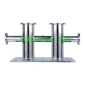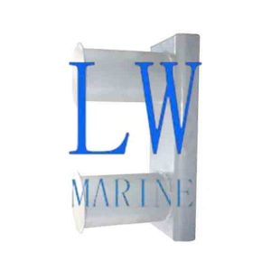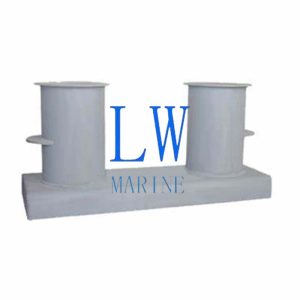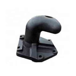
Marine Mooring Post
I. Technical Drawing
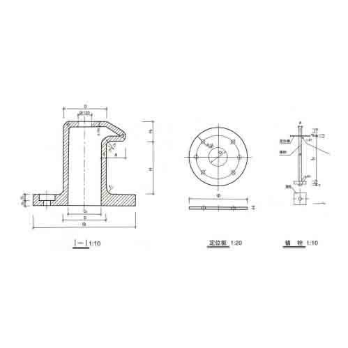
This Marine Mooring Post technical drawing provides a comprehensive set of views for a cast – iron bollard with a round chassis and semi – baffle, including a front view with a sectional view (I – I at 1:10 scale), a location view (1:20 scale), and a plug view (1:10 scale). The main front view is at a 1:10 scale, clearly showing the overall shape, internal structure, and key dimensions of the component.
Table of Dimensional Specifications
| Load (kN) | D (mm) | D0 (mm) | t (mm) | H (mm) | H0 (mm) | H1 (mm) | B (mm) | B0 (mm) | A (mm) | n1 | n – □ | d (mm) | d1 (mm) | d2 (mm) | L0 (mm) | L1 (mm) | a (mm) | B2 (mm) |
|---|---|---|---|---|---|---|---|---|---|---|---|---|---|---|---|---|---|---|
| 250kN | 320 | 250 | 35 | 350 | 144 | 171 | 180 | 203 | 48 | 24 | 4 – □13 | 36 | 42 | 48 | 90 | 105 | 34 | 520 |
| 350kN | 380 | 290 | 40 | 450 | 144 | 190 | 203 | 250 | 57 | 29 | 4 – □13 | 38 | 48 | 54 | 100 | 120 | 38 | 620 |
| 450kN | 400 | 290 | 45 | 490 | 144 | 203 | 203 | 250 | 60 | 30 | 4 – □17 | 42 | 48 | 54 | 100 | 120 | 42 | 652 |
| 550kN | 450 | 330 | 50 | 500 | 144 | 203 | 250 | 330 | 68 | 34 | 4 – □17 | 48 | 54 | 64 | 120 | 126 | 46 | 734 |
Drawing Instructions
- All dimensions in the drawing are in millimeters (mm).
- The dimensional tolerances of each part in the drawing are in accordance with the IT – I 1550kN round -底盘半挡型铸铁系船桩 (round chassis semi – baffle type cast – iron bollard) standard, for example, refer to relevant figures.
- The top of the bollard column should be cast with “250kN”, “350kN”, “450kN”, and “550kN” characters.
- After reaming the bolt holes, asphalt should be applied for anti – rust treatment.
- After installing the bollard, the shell should be filled with cement mortar.
- The surface roughness of the bolt holes should be uniform, with the rest as required.
- Welding should adopt T42 welding rods.
- The outer轮廓尺寸 (outer contour dimensions; likely a translation error, probably meaning unmarked outer dimensions) in the drawing should have a smooth transition without sharp corners.
- The surface of the bollard shell should be painted with red lead and anti – rust paint twice, and the bolt – head surface can be coated with red lead oil.
- The dimension L in the table is L = L0+[0 +8+20].
II. Bill of Materials
The bill of materials lists all the components required for the assembly of the cast – iron bollard with a round chassis and semi – baffle, along with their material, specification, quantity, individual part weight, and total weight under different load conditions (250kN, 350kN, 450kN, 550kN).
| Serial Number | Component Name | Material | Specification | Quantity | Individual Part Weight (kg) (250kN/350kN/450kN/550kN) | Total Weight (kg) (250kN/350kN/450kN/550kN) |
|---|---|---|---|---|---|---|
| 1 | Shell Body | Cast Iron | HT20 – 40 | 1 | 316/380/400/450 | 316/380/400/450 |
| 2 | Bollard Plug | Q235 | M30 M36 | 4 | 11.629/13.697/15.037/16.875 | 46.516/54.788/60.148/67.5 |
| 3 | Nut | Q235 | CB41 – 76 | 4 | 0.602/0.671/0.737/0.847 | 2.408/2.684/2.948/3.388 |
| 4 | Washer | Q235 | CB85 – 76 | 4 | 0.016/0.018/0.021/0.027 | 0.064/0.072/0.084/0.108 |
| 5 | Location Plate | Q235 | See Drawing | 1 | 10.815/11.825/12.85/13.85 | 10.815/11.825/12.85/13.85 |
Attention please: The description might be incorrect, please contact us for confirmation.
Tag: Our other products
Click here to send inquiry via whatsapp