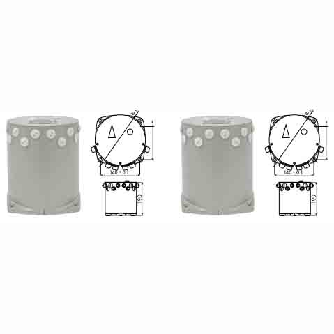
Fiber Optic Magnetic Compass
SF-75 Fiber Optic Magnetic Compass (MFG-L Type)
(Diagram layout provided in the source image)
SF-50 Fiber Optic Magnetic Compass (MFG-III Type)
(Diagram layout provided in the source image)
Configuration Diagram
(Diagram layout provided in the source image)
Sequence shown: Power Supply → Main Compass → Signal Splitter → Display / Repeater Compass
Standard Specifications
| Type | SF-75 | SF-50 |
|---|---|---|
| Power Source | AC 220V / DC 24V | AC 220V / DC 24V |
| Type approvals | CCS | CCS |
| Outside diameter | Φ180mmx190mm | Φ180mmx190mm |
Main Components
| Type | SF-75 | SF-50 |
|---|---|---|
| Main Compass | G1-IB | G1-IB |
| Power Supply Unit | G1-03 (G1-03-2) | G1-03 (G1-03-2) |
| Operation and Display Unit | G1-03 (G1-03-1) | G1-03 (G1-03-1) |
| Interface Box | G1-04 (Optional) | G1-04 (Optional) |
Technical Data
| Type | SF-75 | SF-50 |
|---|---|---|
| Using Temperature | -20℃ ~ +60℃ | -20℃ ~ +60℃ |
| L.M. Settle Point Error | ±0.75° ± 0.5° | ±0.5° ± 0.5° |
| Setting Error | ±0.5° | ±0.5° |
| Compass Safe Distance | 50 | 50 |
| Attitude accuracy | ±0.1° | ±0.05° |
Note: The description may be different with the product, please contact us for quotation.
Click here to contact us via whatsapp for details
Tag: Our other products